


Axial compressors produce higher compression ratios. It is made up of rotor blades and stationary stator vanes The rotor blades are shaped like airfoils. The stator vanes, also designed like an airfoil, are mounted behind each set of rotor blades. They receive the air from the rotor and direct it towards the next stage.

Axial flow compressor
One set of rotor blades and stator vanes constitutes a stage in the axial compressor. Two types of axial compressor engines are commonly found — those so-called single compressors and those with dual compressors.
In dual compressor engine each compressor is mechanically independent on the other, and each compressor has its own turbine. The forward, or low-pressure compressor is driven by rear turbine.
Burner section
About 25% of the air entering the burner section is mixed with fuel for combustion. The rest of the air bypass the fuel nozzle and is used to cool the combustion chamber.
Basically, a jet engine ignition system does not have to be used continuously for extended period of time. Also, jet fuels, at the extremely cold temperatures encountered at high altitudes, require a very hot spark in order to relight the engine in case of a flame out. The sparks used are termed ignitier plugs. Turbojet engines may have as many as 15 separate combustion chambers connected with crossover tubes.
Turbine section
Once the hot exhaust gases and unburned air leave the combustion section, they are directed into the turbine secton. The turbine wheel has to sustain high pressure and temperatures placed upon it.

Single stage turbine
Similar to the compressor, the turbine section may consist of more than one stage. And like the compressor, they are composed of alternating rows of turbing wheel blades and stationary vanes.
Exhaust section
The exhaust section is slightly a trapered tubular duct which connects the turbine outlet to the exhaust nozzle is designed to increase the velocity of the gases.
Turboprop engine
The turbine in this engine is desined to absorb most of the energy from the exhaust gases. Part of this energy turns the compressor, the remaining energy is passed from the turbine to the propeller.

Turboprop engine
However, a reduction gear must be used in order to reduce the RPM (revolution per minute) of a propeller and keep its top speed below that of the speed of sound.
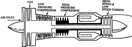
Turbofan engine
The turbofan engine is sometimes referred to as a ducted fan, or bypass engine.
The turbofan engine has one or more rows of compressor blades which extend beyond the normal length. These longer blades are capable of pulling large volume of air through ducts outside the compressor section. This ducted air bypass the cumbustion section. The fan is run directly by the turbine and does not require reduction gearing, as does the turboprop.
The turbofan engine is more fuel economic due to involving larger volume of air for generating thrust.
Turbofan engine
An all-new technology engine is being developed which has 50% fewer parts than other similarly sized engines. It has a fuel authority digital electronic engine control. The use of a specially designed rotor, so-called thermatic TM rotor in the HP (high pressure) compressor saves fuel and contributes to simplier parts design and less assembly time.
The thrust reversers The thrust reversers have been developed in order to minimize the wearing of wheel brakes.

Thrust reverser
Located at the rear of the jet nozzle, this thrust reverser mechanically blocks the exhaust gases and diverts them at an angle whereby the direction of thrust is reversed.
Engine fuels
The qualities required of a gas-turbine fuel include: high heating value, standardized viscosity and density over the range of operating, handling and storing temperatures, low and balanced volatility, absence of corrosive components, absence of impurities which corrode of obstruct, chemical stability. Kerosene is used for aircraft gas turbine engines.
Flight instruments
The main control loops involved in flying airliner are:
Pilotage, which is concerned with the phisical control of the aircraft through the aircraft controls in order to achieve a desired manoeuvre.
Guidance, which provides the date for pilotage.
Flight management is the process of taking decisions on the flight programme to control the flight safety, efficiently and in compliance with ATC instructions.
The altimeter
The altimeter is basically an aneroid barometer which measures the static pressure and indicates the altitude in feet corresponding to this pressure in a defined atmosphere. Altimeters have a sub-scale (correction window) on which any pressure may be set. Various settings available are given in Q-code: QNH, QFE, QNE.

Appearance of typical altimeter indicator
The instrument suffers from five different errors as follows: instrument error, pressure error, barometric error, temperature error, time lag error.
The other type of altimeter carried (the radio altimeter) measures height above terrain and is quite unsuitable for maintaining a constant level over land.
The vertical speed indicator (rate of climb indicator) — VSI
The vertical speed indicator is in a sealed case, and connected to the static pressure line through a calibrated leak. Inside the case is a diaphragm which reacts to changing pressure by either expanding or contracting. This expansion or contraction is represented on the face of the instrument in feet per minute.

Vertical speed indicator
The air speed indicator (ASI) The air speed indicator measures the difference between pitot pressure and static pressure.

Construction of an air speed indicator
The open ended capsule fixed inside an air tight case is connected to a tube called a pitot tube or sometimes pressure head. The pressure produced inside the capsule is the pitot pressure and the other face of the capsule will expand or contract in response to the variations in this pressure.
An ASI suffers from the following four errors: instrument error, position error, density error, compressibility error.
The machmeter
The machmeter is a device which indicates the Mach number. Unlike the ASI the machmeter is an essential equipment in jet aircraft because of speed restriction expressed in Mach number. Machmeters are of course subject to the errors.
The magnetic compass
A simple magnetic compass consists primarily of a magnetic element pivoted well above its centre of gravity so that it rotates in the horizontal plane. The whole is contained in fluid in order to damp oscillations and also to reduce pivot friction by reducing the weight of the rotating unit. The compass card is mounted on the rotating unit and the heading of the aircraft is read-off the compass card against a fixed lubber line.

