


A synchro differential transmitter (TDX) has both a three phase rotor and stator. (Figure below) A synchro differential transmitter adds a shaft angle input to an electrical angle input on the rotor inputs, outputting the sum on the stator outputs. This stator electrical angle may be displayed by sending it to an RX. For example, a synchro receiver displays the position of a radar antenna relative to a ship's bow. The addition of a ship's compass heading by a synchro differential transmitter, displays antenna postion on an RX relative to true north, regardless of ship's heading. Reversing the S1-S3 pair of stator leads between a TX and TDX subtracts angular positions.

Torque differential transmitter (TDX).
A shipboard radar antenna coupled to a synchro transmitter encodes the antenna angle with respect to ship's bow. (Figure below) It is desired to display the antenna position with respect to true north. We need to add the ships heading from a gyrocompass to the bow-relative antenna position to display antenna angle with respect to true north. ∠antenna + ∠gyro

Control transformer
A variation of the synchro transmitter is the control transformer. It has three equally spaced stator windings like a TX. Its rotor is wound with more turns than a transmitter or receiver to make it more sensitive at detecting a null as it is rotated, typically, by a servo system. The CT (Control Transformer) rotor output is zero when it is oriented at a angle right angle to the stator magnetic field vector. Unlike a TX or RX, the CT neither transmits nor receives torque. It is simply a sensitive angular position detector.
Control transformer (CT) detects servo null.
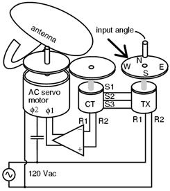
In Figure above, the shaft of the TX is set to the desired position of the radar antenna. The servo system will cause the servo motor to drive the antenna to the commanded position. The CT compares the commanded to actual position and signals the servo amplifier to drive the motor until that commanded angle is achieved.

Servo uses CT to sense antenna position null
When the control transformer rotor detects a null at 90o to the axis of the stator field, there is no rotor output. Any rotor displacement produces an AC error voltage proportional to displacement. A servo (Figure above) seeks to minimize the error between a commanded and measured variable due to negative feedback. The control transformer compares the shaft angle to the stator magnetic field angle, sent by the TX stator. When it measures a minimum, or null, the servo has driven the antenna and control transformer rotor to the commanded position. There is no error between measured and commanded position, no CT, control transformer, output to be amplified. The servo motor, a 2-phase motor, stops rotating. However, any CT detected error drives the amplifier which drives the motor until the error is minimized. This corresponds to the servo system having driven the antenna coupled CT to match the angle commanded by the TX.
The servo motor may drive a reduction gear train and be large compared to the TX and CT synchros. However, the poor efficiency of AC servo motors limits them to smaller loads. They are also difficult to control since they are constant speed devices. However, they can be controlled to some extent by varying the voltage to one phase with line voltage on the other phase. Heavy loads are more efficiently driven by large DC servo motors.
Airborne applications use 400Hz components-- TX, CT, and servo motor. Size and weight of the AC magnetic components is inversely proportional to frequency. Therefore, use of 400 Hz components for aircraft applications, like moving control surfaces, saves size and weight.
Resolver
A resolver (Figure below) has two stator winding placed at 90o to each other, and a single rotor winding driven by alternating current. A resolver is used for polar to rectangular conversion. An angle input at the rotor shaft produces rectangular co-ordinates sinθ and cosθ proportional voltages on the stator windings.

Resolver converts shaft angle to sine and cosine of angle.
For example, a black-box within a radar encodes the distance to a target as a sine wave proportional voltage V, with the bearing angle as a shaft angle. Convert to X and Y co-ordinates. The sine wave is fed to the rotor of a resolver. The bearing angle shaft is coupled to the resolver shaft.
Summary: Selsyn (synchro) motors
- A synchro, also known as a selsyn, is a rotary transformer used to transmit shaft torque.
- A TX, torque transmitter, accepts a torque input at its shaft for transmission on three-phase electrical outputs.
- An RX, torque receiver, accepts a three-phase electrical representation of an angular input for conversion to a torque output at its shaft. Thus, TX transmits a torque form an input shaft to a remote RX output shaft.
- A TDX, torque differential transmitter, sums an electrical angle input with a shaft angle input producing an electrical angle output
- A TDR, torque differential receiver, sums two electrical angle inputs producing a shaft angle output
- A CT, control transformer, detects a null when the rotor is positioned at a right angle to the stator angle input. A CT is typically a component of a servo-- feedback system.
- A Resolver outputs a quadrature sinθ and cosine(theta) representation of the shaft angle input instead of a three-phase output.
The three-phase output of a TX is converted to a resolver style output by a Scott-T transformer.
General Description
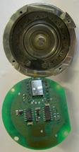
A synchro or "selsyn" is a type of rotary electrical transformer that is used for measuring the angle of a rotating machine such as an antenna platform. In its general physical construction, it is much like an electric motor See below. The primary winding of the transformer, fixed to the rotor, is excited by a sinusoidal electric current AC, which by electromagnetic induction causes currents to flow in three star-connected secondary windings fixed at 120 degrees to each other on the stator. The relative magnitudes of secondary currents are measured and used to determine the angle of the rotor relative to the stator, or the currents can be used to directly drive a receiver synchro that will rotate in unison with the synchro transmitter. In the latter case, the whole device in some applications is also called a selsyn a portmanteau of self and synchronizing. U.S. Naval terminology used the term "synchro" exclusively possible exception steering gear info. needed.
Synchro systems were first used in the control system of the Panama Canal, to transmit lock gate and valve stem positions, and water levels, to the control desks.
Fire-control system designs developed during World War II used synchros extensively, to transmit angular information from guns and sights to an analog fire control computer, and to transmit the desired gun position back to the gun location. Early systems just moved indicator dials, but with the advent of the amplidyne, as well as motor-driven high-powered hydraulic servos, the fire control system could directly control the positions of heavy guns.
Smaller synchros are still used to remotely drive indicator gauges and as rotary position sensors for aircraft control surfaces, where the reliability of these rugged devices is needed. Digital devices such as the rotary encoder have replaced synchros in most other applications.
Synchros designed for terrestrial use tend to be driven at 50 or 60 hertz the mains frequency in most countries, while those for marine or aeronautical use tend to operate at 400 hertz the frequency of the on-board electrical generator driven by the engines.
A synchro or "selsyn" is a type of rotary electrical transformer that is used for measuring the angle of a rotating machine such as an antenna platform. In its general physical construction, it is much like an electric motor (See below.) The primary winding of the transformer, fixed to the rotor, is excited by a sinusoidal electric current (AC), which by electromagnetic induction causes currents to flow in three star-connected secondary windings fixed at 120 degrees to each other on the stator. The relative magnitudes of secondary currents are measured and used to determine the angle of the rotor relative to the stator, or the currents can be used to directly drive a receiver synchro that will rotate in unison with the synchro transmitter. In the latter case, the whole device (in some applications) is also called a selsyn (a portmanteau of self and synchronizing). U.S. Naval terminology used the term "synchro" exclusively (possible exception: steering gear—info. needed).


Fire control system designs developed during World War II used synchros extensively, to transmit angular information from guns and sights to an analog fire control computer, and to transmit the desired gun position back to the gun location. Early systems just moved indicator dials, but with the advent of the amplidyne, as well as motor-driven high-powered hydraulic servos, the fire control system could directly control the positions of heavy guns. [2]
Smaller synchros are still used to remotely drive indicator gauges and as rotary position sensors for aircraft control surfaces, where the reliability of these rugged devices is needed. Digital devices such as the rotary encoder have replaced synchros in most other applications.
Synchros designed for terrestrial use tend to be driven at 50 or 60 hertz (the mains frequency in most countries), while those for marine or aeronautical use tend to operate at 400 hertz (the frequency of the on-board electrical generator driven by the engines).
Selsyn motors were widely used in motion picture equipment to synchronize movie cameras and sound recording equipment, before the advent of crystal oscillators (A crystal oscillator is an electronic oscillator circuit that uses the mechanical resonance of a vibrating crystal of piezoelectric material to create an electrical signal with a very precise frequency. This frequency is commonly used to keep track of time (as in quartz wristwatches), to provide a stable clock signal for digital integrated circuits, and to stabilize frequencies for radio transmitters and receivers. The most common type of piezoelectric resonator used is the quartz crystal, so oscillator circuits designed around them became known as "crystal oscillators.") and microelectronics.
 Acrystal oscillator
On a practical level, synchros resemble motors, in that there is a rotor, stator, and a shaft. Ordinarily, slip rings and brushes connect the rotor to external power. A synchro transmitter's shaft is rotated by the mechanism that sends information, while the synchro receiver's shaft rotates a dial, or operates a light mechanical load. Single and three-phase units are common in use, and will follow the other's rotation when connected properly. One transmitter can turn several receivers; if torque is a factor, the transmitter must be physically larger to source the additional current. In a motion picture interlock system, a large motor-driven distributor can drive as many as 20 machines, sound dubbers, footage counters, and projectors.
Single phase units have five wires: two for an exciter winding (typically line voltage) and three for the output/input. These three are bussed to the other synchros in the system, and provide the power and information to precisely align by rotation all the shafts in the receivers. Synchro transmitters and receivers must be powered by the same branch circuit, so to speak; voltage and phase must match. Different makes of selsyns, used in interlock systems, have different output voltages.
Three-phase systems will handle more power and operate a bit more smoothly. The excitation is often 208/240 V 3-phase mains power.
In all cases, the mains excitation voltage sources must match in voltage and phase. The safest approach is to bus the five or six lines from transmitters and receivers at a common point.
Synchro transmitters are as described, but 50 and 60-Hz synchro receivers require rotary dampers to keep their shafts from oscillating when not loaded (as with dials) or lightly loaded in high-accuracy applications.
Large synchros were used on naval warships, such as destroyers, to operate the steering gear from the wheel on the bridge.
A rotary encoder, also called a shaft encoder, is an electro-mechanical device that converts the angular position of a shaft or axle to an analog or digital code, making it an angle transducer. Rotary encoders are used in many applications that require precise shaft unlimited rotation—including industrial controls, robotics, special purpose photographic lenses [1], computer input devices (such as optomechanical mice and trackballs), and rotating radar platforms. There are two main types: absolute and incremental (relative).
An amplidyne is an electromechanical amplifier invented during World War II by Ernst Alexanderson. It is usually an AC motor driving a DC generator with modifications to increase the power gain available. A small electrical signal can control the position of a large motor using this approach.
An amplidyne is a special type of motor-generator which uses regeneration to increase its gain. Energy comes from the motor, and the power output is controlled by changing the field current of the generator. In a typical generator the load brushes are positioned perpendicular to the magnetic field flux. To convert a generator to an amplidyne you connect what would be the load brushes together and take the output from another set of brushes that are parallel with the field. The perpendicular brushes are now called the 'quadrature' brushes. This simple change can increase the gain by a factor of 10,000 or more.
Historically, amplidynes were one of the first amplifiers to generate very high power (tens of kilowatts), allowing precise feedback control of heavy machinery.Vacuum tubes of reasonable size were unable to deliver enough power to control large motors, but vacuum tube circuits driving the input of an amplidyne could be used to boost small signals up to the power needed to drive large motors. Early (WWII era) gun tracking and radar systems used this approach.
Amplidynes are now obsolete technology. Modern electronic devices for controlling power in the kilowatt include MOSFET and IGBT devices.
In its simplest form, an amplidyne follow-up system consists of:
· a synchro control transformer;
· an amplifier;
· the amplidyne motor-generator, which is similar to a Ward Leonard control drive;
· and the follow-up DC motor which drives the load to be positioned.
"The synchro control transformer receives the order signal which indicates electrically what the position of the load should be. The rotor of the synchro control transformer is turned by the response shaft, which is geared to the load and so indicates what the position of the load actually is. The synchro compares the actual load position with the ordered position; and, if the two do not agree, it generates an alternating-current signal which is transmitted to the amplifier. The angular difference between the two positions is called the error, and the signal to the amplifier is the error signal. The error signal indicates by its electrical characteristics the size and direction of the error. If no error exists, the system is said to be in correspondence and the error signal is zero." [1]
Specifically, the phase of the control transformer's output (in phase with the synchro power source, or opposite phase) provided the polarity of the error signal. A phase-sensitive demodulator, with the synchro AC power as its reference, created the DC error signal of the required polarity.
AMPLIFIER - An electronic circuit that draws power from a supply voltage, or voltage source, to produce, at its output, an increased reproduction of the signal existing at its input. The amplifying component could be a transistor, vacuum tube, or an appropriate magnetic device.

