


New Document
New document: if there is no document before drawing image, many instructions of the software may be unusable and drawing cannot be carried out. Click [File] in menu bar Ўъ [New] order or click the Ў°NewЎ± button in tool bar to newly establish a document.
 or
or 
Figure 3-1
Open
Open files: if there are already drawn PLT, AI, DXF, BMP, DST and DSB graphic files, click [File] in the menu bar to [Open] order or click the Ў°OpenЎ± button in the tool bar to pop up the dialog box.
 or
or 
Figure 3-2
Find the location in dialog box to save files, select a file and open it. There is a preview check box in the dialog box, which could preview the files that are checked.

Figure 3-3
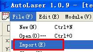
Import
It is able to apply the import function to merge several files into one. Click [File] Ўъ [Import] order in the menu bar or click the Ў°importЎ± button in the tool bar to pop up the import dialog box.
 or
or 
Figure 3-4
Find the location in the import dialog box to save files and import them.

Figure 3-5
Successively import each file and arrange their locations, which could merge all imported files. For instance, merge the two images in the example and the result as follows can be realized.

Figure 3-6
The difference between importing and opening:
Ё№ Open file: there will be a new document established every time when opening a file which cannot be combined with current files.
Ё№ Import file: there will not be a new document established every time when importing a file and itЎЇs able to add image data in current document.
Drawing Lines
Click the  button in the tool bar on the left to start drawing lines.
Click at the drawing area as the beginning of the line and successively click N times to form a line consisting of N-1 segments. [Right Click] to pop up the menu and click [End] or [Enter] or the [Space] button to end drawing.

Figure 3-7
Drawing Rectangles
Click the  tool in tool bar on the left to start drawing rectangles.
Press the left button of the mouth in the drawing area as a point of rectangle, drag the mouth while keeping pressing the left button till another point to form a rectangle with the diagonal of starting and ending points of the left button of the mouth.

Figure 3-8
Drawing Ellipses and Rounds
Click the  tool in tool bar on the left to start drawing rounds or ellipses
Press the left button of the mouth in the drawing area and drag to form a ellipse.

Figure 3-9
Keep pressing the [Ctrl] button in keyboard; afterwards, press the [Left Button] of the mouth and drag to form a round.

Figure 3-10
Entering Texts
Click the  tool on the left side of the tool bar, click the left button of the mouse in the drawing area; afterwards, the dialog box of entering text will appear. Enter texts in the dialog box, set the font and size and then click OK for entering text.


Figure 3-11
Selection
Before editing, select the graph first. Click selection and border selection are optional for selection.
Click selection
Click the  tool on the left side of the tool bar, move the cursor to the contour line of the pixel and click the left mouse button; afterwards, eight small black squares will appear in the periphery of the pixel, representing that the pixel that has been selected. Press the [Shift] button on the keyboard, and perform click selection continuously to select multiple pixels.

Figure 3-12
Border selection
Click the tool on the left side of the tool bar, and click the mouse in the drawing area to draw a dotted rectangle by drag the mouse.

Figure 3-13
After the pixels are framed by the rectangle, release the left mouse button and the pixels are selected, as shown in Figure 3-14.

Figure 3-14
Mirror Image
Mirror image falls into horizontal image and vertical image.

Figure 3-15
Horizontal mirror image
After the selection of pixels, click the Ў°horizontal mirror imageЎ± and all the selected pixels will regard the horizontal center line of the exterior rectangles as the mirror surface to make mirror image.

Front View of the Mirror Image Figure 3-16

Rear View of the Mirror Image Figure 3-17
Vertical mirror image
After the selection of pixels, click the Ў°vertical mirror imageЎ± and all the selected pixels will regard the vertical center line of the exterior rectangles as the mirror surface to make mirror image.
Front View of the Mirror Image Figure 3-18

Rear View of the Mirror Image Figure 3-19
Rotation
After the selection of pixels, enter the angle in the tool bar  in the upper side of the drawing area. Entering positive pixel will lead to clockwise rotation, while entering negative pixel will lead to counterclockwise rotation. Afterwards, press the Ў°EnterЎ± button, and all the selected pixels will rotate with the central point of the exterior rectangles as the rotation point.

Before Rotation Figure 3-20

After Rotation Figure 3-21
Pixel Alignment
Pixel alignment is the operation for two or more pixels.
Left horizontal alignment
After selection of more than two pixels, click the [left horizontal alignment] on the left side of the tool bar  or press the [L] button on the keyboard and all the selected pixels will be left-aligned.

Before Alignment Figure 3-22

After Alignment Figure 3-23

