


1. All modern ship alternators are equipped with voltage regulators. The regulators permit to obtain constant voltage of generators under va≠rious amount of load and power factor.
2. Here we shall speak about AVR for brushless alternators.
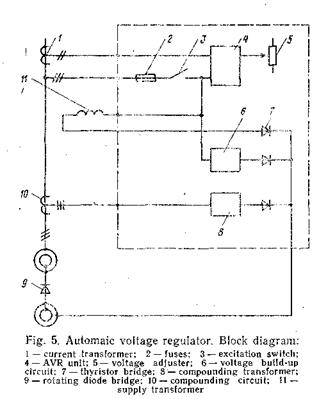
Block diagram (Fig. 5) shows the regulator principle in an autono≠mous alternator system. The alternator voltage is fed to the AVR unit (4) via fuses (2) and exciter switch (3). The reference level of the alternator voltage is set by the voltage adjusting potentiometer (5). The difference between the actual voltage and reference value is ampli≠fied and converted to triggering pulses to the thyristor bridge (7). A-c voltage is fed from the alternator via supply transformer (11) to the thyristor bridge (7).
3. Under normal circumstances, the voltage is kept constant. If speed drops of more than 5% occur, the AVR unit will automatically decrease the voltage proportional to the frequency (U/f-constant).
4. To obtain correct load sharing between parallel running alternators, the alternator' voltage is made current dependent. This is obtained by current transformer (1) and a resistance network inside the AVR unit (4).
5. A voltage build-up circuit which uses the alternators residual magne≠tism provides automatic voltage build-up.
6. The compounding circuit (10) and a compounding transformer (8) provide the necessary excitation current during short circuit conditions when voltage generator is equal to zero. It is necessary for immediate voltage build-up after elimination of short circuit.
The main unit of regulator is AVR circuit. The AVR circuits consist of the following parts: voltage measuring circuit, amplifier, frequency measuring circuit, synchronizing and triggering circuit, stabilized power supply.
All the above mentioned circuits are mounted on a printed board.
7. The alternator voltage is transformed before it is fed to the printed circuit board via terminals. The voltage is rectified and a proportional voltage is fed to an operational amplifier where it is compared to the re≠ference voltage. The difference voltage is amplified and controls, via a triggering circuit, the firing angle of the thyristors and thereby the exciter current.
8. In case of alternator voltage change, the regulator generates a signal which changes the firing angle of the thyristors until the desired voltage is obtained. A stabilizing filter ensures stable and alternator voltage.
power factor Ч кпд, коэффициент мощности, косинус
block diagram Ч структурна€ схема (блочна€)
autonomous alternator systemЧ система с автономным генератором переменного тока
is fed to the AVR unit Ч подводитс€ к блоку ј–Ќ
exciter switch Ч выключатель напр€жени€ возбуждени€
reference level Ч заданный уровень
reference value Ч заданна€ величина
triggering pulse Ч включающий импульс
resistance network Ч цепочка сопротивлени€
voltage build-up circuit Ч цепь восстановлени€ напр€жени€
residual Ч остаточный
transient protection Ч защита дл€ переходных режимов
AVR circuit Ч схема ј–Ќ
voltage measuring circuit Ч измерительна€ цепь напр€жени€
triggering circuit Ч цепь выработки переключающих импульсов
stabilized power supply Ч стабилизированный источник питани€
printed board Ч печатна€ плата
operational amplifier Ч операционный усилитель
difference voltage Ч разностное напр€жение
firing angle Ч угол зажигани€

