


The antenna system has APM horizontal beam shape close to a circle which is offset with respect to the center of APM. Rotation of the diagram at an angular velocity  = 30 rev / s results in amplitude modulation of the received signal with a frequencyiS equal 30 Hz.
.

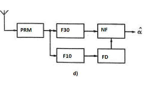
Figure 3.2 The radiation pattern of the antenna phase ARM (a);azimuth signal,received at points 1 and 2 (b); spectrum of the received signal (с);
on board equipment block diagram (d)
The basic equation of ARM that implements phase method of determining azimuth, has the form:
 (3.2)
(3.2)
By measuring the phase of the envelope of the received signal, it is possible to directly determine the azimuth of the point of reception. It follows that the determination of the azimuth error is numerically equal to the phase measurement error.
For phase measurement on LA with APM transmit a reference signal which is frequency-modulated subcarriers with an average frequency oscillations kHz. Modulating voltage signal is at a frequency of 30 Hz at a constant phase corresponding to the phase of the signal received at the workstation from a northerly direction.The onboard equipment of aircraft detected, ARM signal Rx receiver divided filters F30 and F10, respectively tuned to the frequency and. From the reference signal after the frequency detector BH stands constant phase signal with a frequency that is supplied to the IF phase meter, which served as the azimuth signal of the same frequency.
Phase detector computer modeling
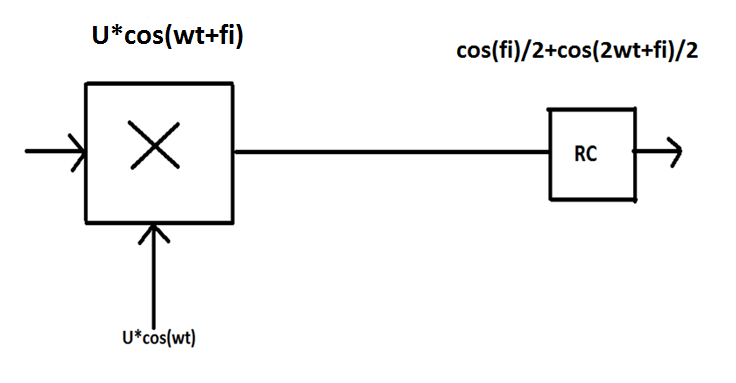
Figure 3.3 Phase detector work principle
The output of the balanced mixer contains twice the frequency of the input signal and a constant component.Here we can use expression 3.1:

and
 (3.3)
(3.3)
Program code
clear all
n=1000; number of sample
T=20; signal period or at the points of reference
ialf=0; initial value loop counter
alf=200; the time constant of low-pass filter is equal to R * C.
for fi=0.01:0.1:1*pi
ialf=ialf+1;
tau(ialf)=2*fi;
for i=1:1:n
x(i)=cos(2*pi*i/T)*cos(2*pi*i/T+fi);
end
y(1)=0;maxy=-1000;
for i=2:1:n
y(i)=(1-1/alf)*y(i-1)+(1/alf)*x(i);
end
ff(ialf)=1*(acos(1*mean(y))-1.15)/0.85*2*pi;
% ff(ialf)=acos(mean(y)/2);
end
% figure(1)
% subplot(2,1,1)
% plot(x)
% grid on
% hold on
% subplot (2,1,2)
% plot(y)
% grid on
% hold on
figure(2)
plot(tau,ff)
grid on
hold on
title('Phase Detector characteristic')
xlabel('Direction of arival')
ylabel('Estimation of arival direction')

Figure 3.4 Phase Detector characteristic
CONCLUSIONS
The basis of short-range navigation systems (SRNS) - a network of independent ground beacons, which defines the parameters of the navigation. There are azimuth, long-range and long-range azimuthal beacons (RM), which is mounted on the ground and in the points corresponding to the characteristic parts of the airways. For RLS allocated plots the range of meter and decimeter waves, so their range of action is limited to a range of line of sight.
|
|
|
Navigation options range navigation systems - bearing and distance are determined on the aircraft with respect to the radio navigation points
Distance determination methods-it is the methods of establishing target distance and placement.Types of ranging include echo,intermittent,manual,navigational,explosive echo,optical,radar,ect.
In calculation part was considered brief information about filters and then filter work was modeled, namely a digital bandpass filters 90 and 150 Hz, whose are installed onto real glide path receiver GRP-2, with using of its real possible characteristics which were got from instruction book.
By obtained results we may conclude, that in case of work of both frequencies, the efficient results are roughly the same. It means that these kind of frequencies (90 and 150 Hz) were picked intentionaly for exlusive use on instrumental landing systems.
On-board equipment azimuth value determined by measuring the phase difference signal frequency of 30 Hz. On board the aircraft except azimuth values determined and reflected in the presence of PS deviation from the line rate with simultaneous display of flight direction relatively tochky location beacon ("On" - "From"). In 4000 VOR beacon provides the ability to transfer voice information on board and radio signals recognition. Radio beacons VOR-4000 can be used both independently and together with the DME beacon creating RSBN type VOR / DME.
The output of the balanced mixer contains twice the frequency of the input signal and a constant component, which is proportional to the phase difference, which follows from the expression:
Sinus small angle is approximately replaced by the angle. Component at twice the frequency can be easily filtered by the LPF.
REFERENCES 1. Melkumyan, V. G., Semenov A. A., Zuiev A.V. Radionavigating systems of the airports. Angle measuring and long-range systems: the manual.-K.:KIUCA, 2000.-196 C. 2. Makarov K. V., and others. Radionavigating systems of the airports: textbook.-M.: Transport, 1988.-344 S. 3. Prokopenko, I. G., Statistical signal processing: textbook.-K.:NAU, 2011.-220C.
4. Belyaevsky L. S., Novikov V. S., P. V. Olenik Fundamentals of radionavigation: Textbook for higher educational establishments of civil aviation.-M.:Transport, 1982.-288 p.
5. Description and instructions for glide path and course radio receivers SRC-2 and IF-F type, designed to operate in the "SP-50" systems and "ILS". - 1960. - 117 p.: fig + scheme.

