


Setting Up the Planetable
When setting up the planetable, spread the tripod legs well apart and press them firmly into the ground. The table should be about waist high so that you can bend over it without resting against it. Level the board by placing the alidade near the center of the table top, loosening the tilting clamp, and tilting the board until the circular level bubble on the alidade is centered. Then tighten the clamp to hold the board in this position. Be careful that the alidade does not slide off the board while making this adjustment. Since few tables are rigid enough to remain level as the alidade is shifted about, no special attempt is made to see that the board is perfectly level each time an observation 1s made.
For the plotted angles to be theoretically correct, the plotted position of the station at which the planetable is set should be directly over the corresponding ground point. The degree of care to he used in bringing the plotted point over the ground point depends on the scale of the map. For small scale map work, place the table over the station without attempting to get the plotted point vertically over the ground point. For large-scale mapping, set the table over the point and orient it approximately by sighting or magnetic needle. Then by plumbing, shift the table until the point on the paper is approximately over the station point.
Then loosen the clamp that keeps the table from rotating and orient the table by rotating it on its vertical axis. Orientation may be done by one of three methods:
1. For making rough, small-scale maps, orientation by means of the magnetic compass is sufficiently accurate. Rotate the table until the fixed bearing (usually magnetic north) is observed, and then clamp it. All mapping at the station is carried on without the board's being disturbed. If the compass is mounted on the alidade, aline the straightedge with a meridian that was drawn at the first station occupied and rotate the table until the needle
points north. Orienting with the magnetic needle has an advantage over other methods in that an error in the plotted direction of one line will not introduce a systematic error in lines plotted from succeeding stations. The disadvantages are the impossibility
of determining the exact point on the graduated arc at which the needle comes to rest;
magnetic variations due to local attractions or other causes; and sluggish needles, bent pivots, or bent needles.
2. The table can also be oriented by backsighting along an established line that has been previously plotted. The advantage of this method lies in the increased precision obtained in orientation. A disadvantage is that the error in any previously plotted line is transferred to succeeding lines. This is the method generally used on intermediate and largescale
mapping.
3. The table can also be oriented by the application of the principle of resection. This method is used to determine the position of any point on the map corresponding to the location of the point on the ground over which the planetable is set. Three established ground points must be visible from the point in question, and the positions of these three
|
|
|
points must have been located on the map. Be sure to establish the direction of the magnetic meridian on the sheet before attempting to solve the three point problem.
Assume the planetable is set up on an unmapped ground point D, and points A, B, and C, whose positions a, b, and c are plotted on the sheet, are visible from D. The problem is to find the location of d on the sheet corresponding to D on the ground. This location of d is found by trial. The planetable is oriented by estimations of point D (fig. 1-38).
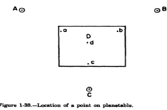

If this estimated orientation is correct, resection lines from A, B, and C would intersect at assumed point d. A resection line is drawn on the sheet with the edge of the alidade at point a and a sight taken on point A. Similar lines are drawn on the sheet with the edge of the alidade at b and c, and sights are being taken on B and C. As the table, however,
was oriented at D by estimation, these resection lines will not intersect at point d but will form a triangle of error a', b', c' (fig. 1-39). The size of this triangle will depend on the degree of error in orientation.
Usually, after some experience, two attempts are sufficient to orient the planetable and find the plotting position of d. In estimating the correct position of the point on the sheet from the triangle of error, keep in mind the following geometric relations(fig. 1-39):
1. When D is within the triangle, abc, the point d will fall within the triangle of error, and will be farther from the line from the furthermost point than from either of the lines from the other two points.
2. When D is outside the triangle abc but within the circle prescribed by the points of this triangle, d will fall outside the triangle of error, and is on the side of the line from the middle point opposite the intersections of the lines from the other two points.
3. When D is outside the circle prescribed by the points of the triangle abc, d is outside the triangle of error and on the same side of the line from the most distant point as is the intersection of the lines from the other two points.
4. In every case, the distance d is from a resection line is proportional to the distance D is from the point from which the resection line is drawn. After orienting the instrument, observe the direction of lines by rotating the alidade until the line of sight corresponds to the line to be observed. If stadia rods are used, read the distance and plot it to the scale of the map. Elevations can also be determined and plotted. If the alidade is equipped
with a Beaman arc, the computations for true horizontal distance and corrected elevations are simplified.
If objects (buildings, trees, etc.) only are to be located, establish their position by drawing rays L from two previously plotted points. The intersection of the rays establishes the location of the objects
Lesson 31
Mapping Procedures
Mapping with the telescopic alidade and planetable consists of the following steps:
1. Set up the planetable on its tripod in a strategic location so that as much as possible of the area to be mapped is visible. Readings accurate enough for average mapping can be taken up to 450 m (1,500 ft) on cloudy days, but less in bright sunlight. Distances should not exceed 300 m (1,000 ft) if elevations also are to be obtained.
|
|
|
Heavy paper should be used on the drawing board, preferably dull buff or green to reduce glare.
2. Level the table with the bubble or bubbles provided on the base plate of the alidade. Tighten the upper clamp of the tripod head to secure the table in the horizontal plane.
3. Orient the table with the area to be mapped. If this is the initial setup, rotate the table around its vertical axis until the long axis lies in the same direction as the long axis of the area to be mapped. Then tighten the lower clamp, which holds the table in position.
4. Select the scale for mapping. A suitable scale for most topographic mapping is 1:2,400, which is 1 cm = 24 m (1 in = 200 ft). When greater detail is desired, a scale of 1:1,200 [l cm = 12 m (1 in = 100 ft)] may be used.
5. Next, locate the planetable position on the sheet of drawing paper. Estimate the principal dimensions of the area to be mapped and locate its approximate position on the drawing board by means of the scale. Next, determine the approximate position of the planetable by a pinpoint on the board. (A sewing needle is preferred to a pin or
small tack because of its thinner taper and greater strength.)
6. With the alidade set in position, release the north arrow and rotate the alidade until the arrow comes to rest under the zero of its scale. The telescope is now pointed to magnetic north, and you can draw the magnetic north line on the map by use of the straightedge. This line is useful for rough orientation later and should be left on the map. Use a hard lead pencil (at least 4H) or nonsmear plastic lead in planetable work. Moving the alidade around over the paper will smear a softer lead.
7. Plot points on the drawing board by the following procedure: Sight the telescope on a rod held at the selected point, keeping one edge of the straightedge against the needle, which represents the map position of the instrument position on the ground.
Observe the distance from the instrument to the point. Using an engineer's scale, measure this distance on the map along the line of sight and then plot the point. Distances may be measured on the ground by pacing, chaining, or by stadia. Usually, this measurement is by stadia rod set on points to be plotted on the map and observed on the vertical crosshair of the alidade. When elevations also are to be obtained, first an HI must be established
by taking a backsight on a BM of known elevation. Then set the vertical hair on the rod, level the bubble tube, and read the middle crosshair and one of the stadia hair intercepts on the rod. The middle crosshair reading gives the elevation, and by multiplying the interval between the two rod readings by two, you can find the stadia interval. Because one person can map faster than another can move around to the points to be mapped, a better balanced crew would have two people using rods.
8 If the area is to be gridded, and this is often the usual way to obtain the necessary information, measure distances between shots by pacing and then plot on the map. Care should be taken by the rodholder to retest representative points for plotting
contours.
9 After all information has been obtained for the setup, move the instrument to a new location. Before moving, take a foresight to the new location and plot the point on the map. Take an elevation turn about midway to the new setup. After moving the instrument to the new station and leveling up the table, orient the instrument by laying the straightedge along the line on the map from the new to old instrument stations and rotate the table
until e vertical crosshair in the telescope falls on the rod held at the previous station. Again tighten the table clamp, and the instrument is oriented. The HI is picked up by taking a backsight on the elevation turn set before the move. A set of differential
level notes should be kept of the readings taken on bench marks and turning points, carefully describing each.
10. Should the location of instrument stations become lost either on the ground or on the map, the planetable can be oriented as previously described or by other methods described in surveying texts.
Lesson 32

