


The ELT supplies these signals:
Ј ELT ON
Ј LIGHT
Ј RF OUT (2).
The ELT ON and LIGHT signals go to the ELT control panel. The ELT has two transmitter sections, one for the 121.5/243.0 MHz signal, and one for the 406 MHz signal. The two transmitter sections send the RF emergency signals to the ELT antenna on different transmission lines.
The ELT receives these signals:
Ј EXT ON
Ј RESET 1 and RESET 2.
The EXT ON signal from the control panel manually starts the transmitter.
The reset signals stop the transmitter if it accidentally starts. A G-switch enable jumper wire arms the ELT when you connect the front connector.
ELT Antenna
The ELT antenna sends the emergency signals on the VHF and UHF frequencies.

Purpose
The emergency locator transmitter (ELT) control panel lets you monitor and do a test of the ELT.
Indication
The ELT control panel has an ELT light. The light comes on when the ELT transmits.
Control
The ELT control panel switch has an ON and an ARM position. The ON position manually turns on the transmitter. The ARM position is the normal position for flight.
The switch has a guard to keep it in the ARM position.

Purpose
The emergency locator transmitter (ELT) sends emergency signals when it sense excessive change in velocity.
Power
The transmitter operates with four D-cell, lithium manganese dioxide batteries. The transmitter does not use airplane power.
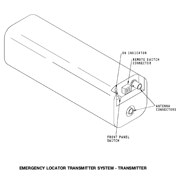
Front Panel
The ELT front panel has a switch and an ON indicator.
The front panel switch has two positions. The ON position manually turns on the transmitter. The OFF position is the normal position. When the switch is in this position, the transmitter starts when one of these occurs:
Ј Large change in velocity
Ј ELT control panel switch is in ON position.
The ELT ON indicator flashes when the transmitter is on.
The antenna connectors connect the ELT to the antenna.
The remote switch connector connects the ELT to the ELT control panel.
TRANSMITTER
Purpose
The emergency locator transmitter (ELT) antenna sends radio signals in the very high frequency (VHF) and ultra high frequency (UHF) ranges.
Physical Properties
The antenna is a dual element antenna with two coax connectors.
The 121.5 MHz and 243.0 MHz ELT transmissions come in on the BNC series connector.
The 406 MHz transmissions come in on the TNC series connector.
ANTENNA

General
The emergency locator transmitter (ELT) has these components:
Ј Latching circuit
Ј Microprocessor
Ј 121.5/243.0 MHz transmitter
Ј 406 MHz transmitter
Ј G switch
Ј ON light
Ј ELT switch
Ј Battery pack.
ELT Transmitter Inputs
The ELT receives these inputs from the control panel:
Ј EXT ON
Ј RESET 1
Ј RESET 2.
ELT Transmitter Outputs
|
|
|
The ELT has these outputs:
Ј RF OUT (2)
Ј ELT ON
Ј LIGHT.
The ELT send the RF outputs to the antenna.
The ELT sends the LIGHT and ELT ON signals to the control panel when the ELT transmits. The LIGHT signal turns on the ELT light on the control panel. The ELT ON signal turns on the master caution lights.
Normal Operation
In normal operation, the ELT control panel switch is in the ARM position and the ELT transmitter front panel switch is in the OFF position. In this condition, the ELT is not active. The control panel, the ELT front panel, and the master caution lights are off.
ON Operation
To go from normal (ARM) to ON operation, the ELT needs a change of switch position from one of these sources:
Ј G-switch
Ј Control panel switch
Ј ELT front panel switch.
A G-switch jumper wire prevents the ELT from accidental operation while the unit is in transit to the airplane.
The jumper wire arms the G-switch only when the unit front connector is connected. When the switch is armed, the switch changes position when it senses a large change in velocity.
The control panel switch lets you manually start ELT transmission. When you put the control panel switch to ON, an EXT ON signal goes from the control panel to the ELT. This signal manually starts the transmitter from the control panel.
The ELT front panel switch also lets you manually start the transmitter. You do this when you put the front panel switch to ON.
The latching circuit holds the ELT on when it receives a change in switch position. This circuit sends a signal to the processor and the front panel ON indicator. When the ELT is on, the processor commands the two transmitters to send the emergency signals. The ON indicator flashes continuously.
A transmitter uses 121.5 MHz and 243.0 MHz carrier frequencies. This transmitter sends both frequencies at the
same time on the same transmission line. These frequencies are amplitude modulated with an audio frequency. This audio frequency sweeps continously from about 1600 Hz to 300 Hz.
This gives a homing signal for the search and rescue personnel.
Search and rescue satellites detect the 121.5 Mhz and 243.0 Mhz transmissions and send these signals back to ground stations. The ground stations receive and process the 121.5 MHz signal to find the location of the ELT. It gives a location accuracy of about 20 km.
The 121.5/243.0 MHz transmitter operates until the battery pack becomes unserviceable. The battery pack power lasts for at least 72 hours.
The other transmitter uses a 406.0 MHz carrier. This transmitter gives information to locate and identify the ELT.
The processor
The processor synchronizes the operation of both transmitters. Only one transmitter is on at a time. Every 50 seconds, the processor turns off the 121.5/243.0 transmission for a short time (440 msec) and commands the 406.0 MHz transmitter to send its signal.
Satellites detect the emergency signals from the 406.0 MHz transmitter and send this information to ground stations. The ground stations receive and process the emergency signals to find the location of the ELT. The 406.0 MHz transmitter gives a location accuracy of about 3 km.
The 406.0 MHz transmitter also give this information for the search and rescue personnel:
Ј Serial number of the ELT
|
|
|
Ј Country code
Ј ELT manufacturer.
The 406.0 MHz transmitter operates for 24 hours and then shuts down to conserve power.
Reset
The RESET 1 and RESET 2 inputs from the control panel let you turn off the transmitter when it comes on accidently. These inputs turn off the transmitter when you put the control panel switch from ARM to ON and immediately back to ARM.
You can also turn off the transmitter when you put the ELT front panel switch from OFF to ON and immediately back to OFF.


