


ѕор€док решени€

|
| –ис. 1.7. √рафическое окно со схемой проекта в начале счета в Workbench |
1. ѕодготовительные операции
ѕуск → ¬се программы →
→ ANSYS 12.0 → Workbench →
→ Component System (Ћ ћпо
знаку ⊞) → CFX (2 Ћ ћ) →
→ Mesh (2 Ћ ћ)
ѕо€в€тс€ блоки ј и ¬ схемы проекта (рис. 1.7).
2. »мпорт геометрии
Geometry (ѕ ћпо €чейке в
блоке ¬) → Import Geometry →
→ Browse → ќткрыть файл с
геометрической моделью
(«десь файл ЂBurner tube in tubeї) → Mesh (ѕ ћпо нижней €чейке блока ¬) → Edit → ќткроетс€ окно Meshing с геометрической моделью камеры стенда (рис. 1.8).
3. «адание регионов
†Ц –егион суммарного входного отверсти€ горелки:
⊞ Regions (ѕ ћ) → Insert →
→ Composite 2 D Region →
повернуть модель при нажатом Scroll, сделать видимым горелочный торец камеры. ¬ыделить с помощью Ctrl окружность и кольцо на торце модели горелки (рис. 1.9, а).
→ Apply (Ћ ћв окне Details View слева внизу) → Ћ ћпо надписи
†ЂComposite 2 D Region 1ї (или ѕ ћ по этой надписи и выбрать Rename) → ¬писать Inlet → Enter (рис. 1.9, б).

|
| –ис. 1.8. „асть экрана с геометрической моделью стенда в сеточном генераторе |

| 
|
| а | б |
|
–ис. 1.9. ќпределение региона INLET: †а Ц выделение входных отверстий горелки; б Ц ввод имени региона | |
†Ц –егион выходного отверсти€ камеры:
⊞ Regions (ѕ ћ) → Insert → Composite 2 D Region →
ѕовернуть модель при нажатом Scroll, сделать видимым выходное отверстие камеры. ¬ыделить выходное отверстие
→ Apply (Ћ ћслева внизу) → Ћ ћ по надписи ЂComposite 2 D Region 1ї → ¬писать Outlet → Enter.
»зображение на графическом экране показано на рис. 1.10.

|
| –ис. 1.10. «адан регион выходного отверсти€ камеры OUTLET |
Ц –егион стенки камеры:
⊞ Regions (ѕ ћ) → Insert → Composite 2 D Region →
¬ыделить с помощью Ctrl поверхности, составл€ющие стенку камеры, использу€ Scroll.
→ Apply (Ћ ћ слева внизу) → Ћ ћ по надписи ЂComposite 2 D Region 1ї →
¬писать Wall → Enter.
¬ид экрана на стадии завершени€ задани€ региона Wall показан на рис. 1.11.

|
| –ис. 1.11. Ёкран при завершении задани€ региона WALL |
4. «адание сетки
оманды управлени€ генерацией сетки расположены в разделе Mesh дерева проекта (Tree View).
Ћ ћ по знаку ⊞) → †→ Default Body Spacing → ¬ разделе Details View (слева) должно быть задано значение Maximum Spacing. ќставить значение 0.21, предложенное программой → Enter
† → Default Face Spacing → ќставить в разделе Details View значени€, предложенные программой → Enter.
† → Generate Surface Meshes (над графическим окном) → ѕо€вилась сетка на поверхности модели.
|
|
|
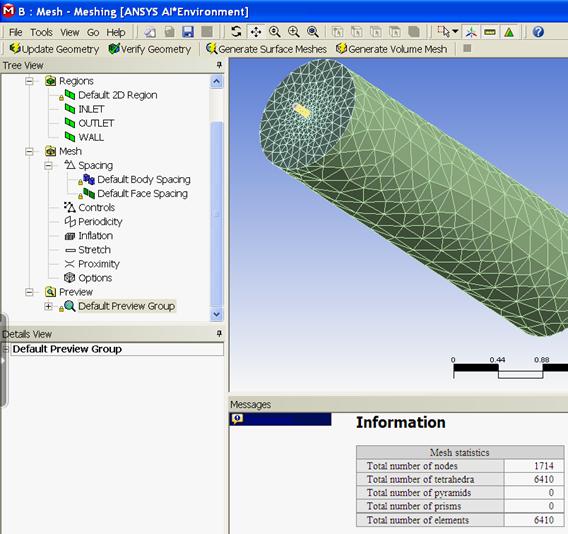
†→ Generate Volume Mesh (над графическим окном) → Ќа экране по€вилась объемна€ сетка на модели камеры (рис. 1.12) и информаци€ о параметрах сетки, общее число элементов которой равно 6410. —етка, сгенерированна€ программой, состоит из €чеек с размерами, мен€ющимис€ по объему.
|
| –ис. 1.12. »зображение объемной конечно-элементной сетки и информаци€ о ее параметрах |

|
| –ис. 1.13. √рафическое окно со схемой проекта в начале счета в Workbench |
5. —охранение сетки, закрытие раздела, передача сетки в CFX
Ц  †—охранить (вверху) → ѕерейти в папку C / calc. CFX. «адать им€ файла. «десь: ЂGORELKA_GNPї → —охранить при заданном типе файла Workbench Project Files (*.wbpj).
¬ид схемы проекта в графическом окне показан на рис. 1.13.
†Ц  (Ћ ћв блоке ¬, нажать и перетащить в €чейку ј2, где Setup).»зменилс€ вид схемы проекта (рис. 1.14) → Setup (ѕ ћв €чейке ¬2) → Edit → ѕредупреждение Workbench → OK →
→ A: Mesh - Meshi Е (Ћ ћпод графическим окном) → ⊠ «акрыть (Ћ ћ вверху справа).«акрываетс€ сеточный генератор ANSYS Meshing →
†††††††††††††††

|
| –ис. 1.14. —хема проекта с передачей данных |
†
→ Update Project (Ћ ћнадграфическим окном) → ѕредупреждение Workbench → OK → Setup (ѕ ћв €чейке ¬2) → Edit.
¬ыполнен переход в препроцессор CFX - CFX - Pre. ѕо€вилось изображение в рабочем окне, показанное на рис. 1.15.

|
| –ис. 1.15. —хема геометрии камеры с горелкой в препроцессоре |
†
6. «адание материалов и математической модели
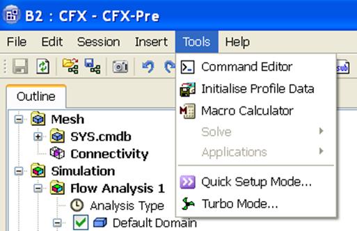
Tools (¬ меню CFX - CFX - Pre, показано на рис. 1.16) → Quick Setup Mode («адаетс€ режим быстрой установки, где часть параметров определ€етс€ по умолчанию) →
|
| –ис. 1.16. ¬ыбор режима быстрой установки параметров |
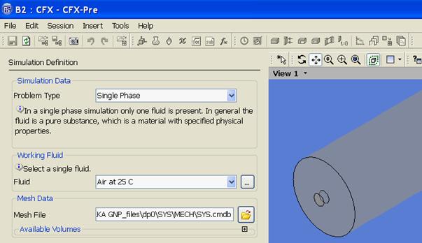
→ ¬кладка Simulation Definition. «адать значени€:
Simulation Data Ц Single Phase;¬ыбрать рабочую среду (Working Fluid). «десь Fluid Ц Air at 25 C (рис. 1.17, а) → Next →.
→ ¬кладка Physics Definition. «адать значени€:
Analysis Type Ц Steady State;Reference Pressure Ц 1 [atm];Heat Transfer Ц Thermal Energy;Turbulence Ц
k-Epsilon (рис. 1.17, б) → Next →.
7а. «адание граничных условий
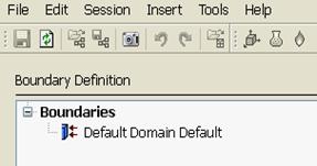
Default Domain Default (ѕ ћ) (рис. 1.18) → Delete Boundary (”дал€етс€ информаци€, котора€ размещалась программой Ђпо умолчаниюї) →
† Ц → Boundaries (ѕ ћ в окне Boundary Definition слева) → Add Boundary Е → ввести им€ INLET в окно New Boundary → OK →
→ ¬кладка Boundary Definition. «адать значени€:
Boundary Type Ц Inlet;Location Ц INLET;Flow Specification Ц Normal Speed;Normal Speed Ц 20 m s^-1;Static Temperature Ц 1500 C. ¬кладка показана
†на рис. 1.19.
|
| †а |

|
| б |
| –ис. 1.17. «адание параметров задачи: а Ц свойств среды во вкладке Simulation Definition; б Ц физической модели во вкладке Physics Definition |
|
| –ис. 1.18. ”даление информации Ђпо умолчаниюї |

|
| –ис. 1.19. «адание граничных условий в регионе INLET |
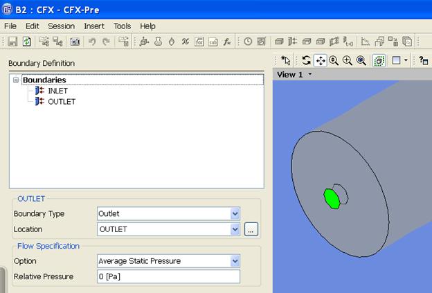
Ц →Boundaries (ѕ ћ) → Add BoundaryЕ → ¬вести им€ OUTLET → OK → ¬кладка Boundary Definition. «адать значени€:
|
|
|
Boundary Type Ц Outlet;Location Ц OUTLET;Flow Specification Ц Average Static Pressure;Relative Pressure Ц 0 [Pa]. «аполнение позицийвкладки показано на рис. 1.20.
Ц →Boundaries (ѕ ћ) → Add BoundaryЕ → ¬вести им€ WALL → OK → ¬кладка Boundary Definition. «адать значени€:
Boundary Type Ц Wall;Location Ц WALL;Wall Influence On Flow Ц No Slip Wall. ¬идвкладки показан на рис. 1.21. → Next.
7б. ѕереход в основной режим
¬вести Enter General Mode (Ќа вкладке Final Operations) →Finish (Ћ ћслева внизу).Ќа рис. 1.22 показано текущее изображение на экране.
|
| –ис. 1.20. «адание граничных условий в регионе OUTLET |

|
| –ис. 1.21. «адание граничных условий в регионе WALL |

|
| –ис. 1.22. ¬ид экрана после задани€ граничных условий |
7в. ѕроверка данных расчета и закрытие препроцессора
ѕеред запуском вычислений исходные данные расчета должны провер€тьс€. ƒелать это удобно после двойного щелчка Ћ ћ по имени региона в разделе Default Domain вкладки Outline. ѕри этом по€вл€ютс€ соответствующие вкладки с граничными услови€ми, аналогичные рис. 1.19, 1.21. ¬ид вкладок соответствует основному режиму General Mode, поэтому информаци€ в них более подробна, чем на рис. 1.19, 1.21.
→  †—охранить → ⊠ «акрыть (Ћ ћ вверху справа).
¬ графическом окне по€вилась видоизмененна€ схема проекта (рис. 1.23)

|
| –ис. 1.23. —хема проекта после задани€ граничных условий |
8. «апуск решени€
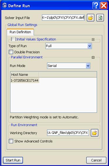
→ Solution (2 Ћ ћпо €чейке ¬3 схемы проекта на рис. 1.23) → Start Run в по€вившемс€ диалоговом окне Define Run (рис. 1.24).
|
| † –ис. 1.24. ƒиалоговое окно запуска вычислений |
| ѕредупреждение. ≈сли по€вилось сообщение ANSYS Workbench ЂThe SFX Solver for system SFX did not produce a results file. No output file is available. Cell B3ї → OK. †→ ⊠ «акрыть (Ћ ћ вверху справа) → Yes (¬ ответ на предложение сохранить модифицированный проект). †Ќа экране по€вилось окно Windows. †→ ќткрыть файл проекта в Windows: C:/ calc. CFX / GORELKA GNP _ files / dpo / CFX / CFX / CFX. def → ѕо€вл€етс€ диалоговое окно Define Run (рис. 1.24). †→ Start Run. |
†
→ ¬ыполн€ютс€ вычислени€. ѕосле их завершени€ по€вл€етс€ изображение на экране, показанное на рис. 1.25.
† → ѕоставить птицы в разделах изображени€  † и
† и  → OK.
→ OK.

|
| –ис. 1.25. ¬ид экрана после завершени€ счета |
9. ѕросмотр результатов в постпроцессоре
¬ид экрана после выхода в постпроцессор показан на рис. 1.26.
† Ц ѕостроение линий тока газов в камере.
 † →
† →  † (или нажать
  †в главном меню) → ¬вести им€ объекта (или согласитьс€ с именем, предложенным программой) →.
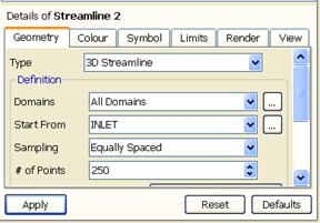
Ќа кладке Detail of Streamline ввести:
Ц в разделе Geometry параметры, показанные на рис. 1.27, а;
Ц в разделе Colour параметры, показанные на рис. 1.27, б → Apply.

|
| –ис. 1.26. »зображение на экране в постпроцессоре |
| 
|
| а | б |
|
| |
| в | |
| –ис. 1.27. ѕостроение линий тока газов в камере: а Ц ввод данных в окна раздела Geometry; б Ц ввод данных в окна раздела Colour; в Ц распределение линий тока в камере | |

ѕолученна€ объемна€ картина движени€ газов в камере показана на рис. 1.27, в. Ќа рисунке видно, что в камере образовались два крупных контура циркул€ции газов. ¬ первом от горелки контуре газы движутс€ к выходу вдоль оси камеры, а во втором Ц вблизи стенок. Ќа рис. 1.27, в дл€ нагл€дности показана сначала только нижн€€ часть линий тока, а затем Ц только верхн€€.

