


List
| Characteristics................................................................. | ||
| Stipulation................................................................. | ||
| Technical Data............................................................. | ||
| Structure and installation................................................... | ||
| 4.1 outside drawing............................................................ | ||
| 4.2 inside construction drawing.................................................. | ||
| 4.3 installation dimension drawing.................................................. | ||
| 4.4 external wiring requirement.................................................... | ||
| 4.5 external terminal layout drawing.............................................. | ||
| From installation to operation..................................................... | ||
| Basic functions............................................................. | ||
| 6.1 start up.................................................................. | ||
| 6.2 register external device....................................................... | ||
| 6.3 fire alarm............................................................... | ||
| 6.4 monitoring information...................................................... | ||
| 6.5 associate operation information................................................. | ||
| 6.6 fault alarm.......................................................... | ||
| 6.6.1 main power supply fault.................................................. | ||
| 6.6.2 back-up power supply fault................................................ | ||
| Menu operation function........................................................ | ||
| 7.1 device information.......................................................... | ||
| 7.2 register information.......................................................... | ||
| 7.3 event record......................................................... | ||
| 7.4 adjust time.......................................................... | ||
| 7.5associated setup................................................. | ||
| 7.5.1УorФ1 logic setup............................................... | ||
| 7.5.2УorФ2 logic setup............................................... | ||
| 7.5.3УandФ logic setup................................................. | ||
| 7.5.4 pulse mode module ..................................................... | ||
| 7.6 system setup.......................................................... | ||
| 7.7 exit....................................................................... | ||
| System self-check.......................................................... | ||
| Lock key/Unlock.......................................................... | ||
| Automatic/Manual switch......................................................... | ||
| Associated contro l ......................................................... | ||
| Repair and Maintenance.................................................. | ||
| Notice............................................................. | ||
| Our service........................................................... |
|
|
|
|
|
|
|
|
|
|
|
|
Hello!
Welcome to Brightsky World! Connecting newest technology 5iserise fire alarm system that will
|
|
|
Exceed your imagination :directly and plenty figure interface you will be the first time to feel our productsТ reliability,The speed of fire alarm system is quicker than before, Brightsky Electronic
Co., Ltd quests system reliability and accurately that will be embodied completely.
This customer manual will let you know the super function of this kind of machine step by step.
Characteristics
² Graphic menu operation, new design
² Black box record function
² Detector condition display
² 250 intelligent bus device points capacity
² Alarm address information second-conversion accurate locating fire address(can input in the form of pre-programming at desk computer or laptop)
² All fire protection linkage operation relationship on-site programming
² Standard 485 interface, LAN network and remote communication function
Our Stipulations
In below descriptions:
² all  display letter or icon is button,For example:
  this is Down button ,
  this is Reset button.
² Bus equipments which are including heat detectors, smoke detectors, manual call points, signal input module etc fire alarm touching equipments and Long-range control module etc Linkage control equipments.
² According to habit or descriptionТs requirements,It will be possible to useУDetectorФletter can take place smoke detector, heat detector, manual call point, signal input module etc fire alarm touching equipments。
² In the system, from No.001 to No.250, it is standard device address (detector, remote control module, etc), from No.251 to No.256, it is six multi-line control modules.
Technical Data
| Main Power:: | AC 220V (+10%~-15%) ,50HZ |
| Back-up power supply: | DC 24V,2.3AH(built in) |
| Work consumption: | Monitor state:≤2.4W;Alarm state:≤10W |
| Basic monitoring capacity: | 5i series addressable device 250 pieces |
| Direct external control contact: | 6 pairs |
| Polling cycle: | ≤10 second(when Condition abnormity, single point continues to poll) |
| Signal transportation distance: | ≤1500 meters. |
| Wiring method: | 1、 5i series detectorsЧЧ2-wire bus, non-polarity; 2、 5i series modulesЧЧ2-wire bus, polarity(T+ЧЧanode,T-ЧЧcathode); |
| Wire application: | RVS-2×1.5mm2 two color plastic soft wire. |
| Outside control touch points: | KA1,KA2 first time alarm, then closed immediately. YA1,YA2 first time alarm under nobody controlled machine delay 2 minutes closed. |
| Outside control touch points capacity: | DC 30V,2A. |
| Operation Environment Temperature: | 0℃~55℃ |
| Relatively humidity: | ≤95% |
| External dimension: | 440×340×82(H×W×T)mm3 |
| Installation form: | Wall mounted type |
| Weight: | About12Kg |
| Black box record data: | Be able to save 500 records(including open, close, alarm, fault and linkage information) |
| Linkage programming amount: | 150 items(or one, or two, with logic 50 items) |
| Room number conversion capacity: | 250 pieces |
| Room number conversion maximum allowable characters numbers: | 30 pieces English characters |
Structure and installation
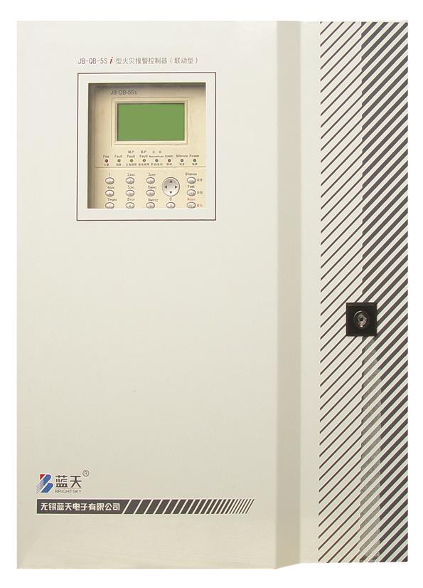
This control use wall mounted structure,There are 2.3Ah all sealed battery. Structure compact, Placement reasonably, Outline beautiful.
This is outline structure figure:
This is the picture after you open the control panel front face:
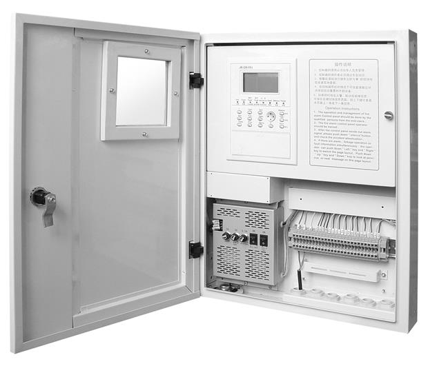
 |

Fire alarm controller should be installed in a room or place where can be controlled by man,at the same time please install fire alarm controller on the wall. Normally fire alarm controllerТs bottom is far away from the ground 1.5 meters,It will leave more than 0.5 meter distance in two sides. So that it will be easy operate and maintenance.
This is installation dimension drawing:

Outside wiring requirements:
Signal wire is used RVS-2×1.5mm2 two colors plastic soft wire,Power wire is used cross-sectional no less than 2.5mm2 inhibit wire.
External wiring terminal layout drawing: 
Directly output point button is one by one hardware button,Though the controllers are УdeadФ, It can also start outside devices.
From installation to operation
1、 Please be carefully to read this manual.
2、 According УinstallationФchapter,install this controller.
3、 Using K ohm metes alarm bus is connecting ground resist must be more than 20K ohm,According to fire extinguishing norm requirements to install detectors, Meanwhile,According to position array figures, in order to check whether wiring is right or not,Each of hardware whether is solid or not.
4、 Start up.
5、 According to fire code and project linkage operation relationship requirement, edit linkage operation relationship list based on Уlinkage operation programmingФsection.
6、 Re open the panel, according to Уregister external deviceФ section, register external devices.
Basic functions
Start
First time start please press control panel  button,Meanwhile please press main/ reserved power switch,After controller initialized, indicator and sounder check itself,Then all devices of bus are loading(at the moment let loose ),It takes about 2 minutes. Then system comes to normally monitor and control state,Power of indicate in controller flashes. Attention:Each time restart system linkage is manually state,at the moment automatic/manually indicator always flashes.。

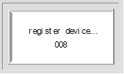
Register outside devices
Register outside devices include to register detectors, modules etc connect with bus devices in the return circuit. Register operating, after start the controller,Press controller power switch,when controller panel indicator flashes. Press register,after finish to register, then indicate to have registered bus devices number and address code. Press  or You can check the detailsТ listing,Press return to monitor and control state.
Fire alarm
Under normally monitor and control state, the controller patrols registered each of detectors,monitor each of detectors current smoke consistency or temperature value,then using the data to calculate and recognize by formula. Using the data according to formula calculate and recognize. If it is be fit for fire alarm condition,it can be put into fire alarm state. At the moment,the controller sounds the alarm,the controller panelТs fire alarm indicator flashes,the displayer indicates alarm address, number etc information,printer(when you install this printer)can print alarm address, alarm time,Meanwhile the outside controller position KA1、KA2 closed,YA1,YA2 begin to delay,If nobody controls controller(reduce sounder or reduce)this position closed. If linkage position is in the automatic state,the controller is according to be the first time addressable linkage logic relation which can set out command in order to start corresponding long-range control module,so that start or close outside devices.(For example fire pump)。 System uses different pages approach among fire alarm, linkage and default information ,If there are two or many kinds of alarm information exist at the same time,Please press  or
or  switch to another fire alarm type page, Press or you can check the up or down information.。
Therein:
fire alarm page displays fire detector, manual call point, etc alarm information

